Latch circuits Motor diagram control wiring circuit wire motors phase basics controlling diagrams three switch sponsored links Motor circuit dc speed pwm controller control circuits simple diagram brushed 555 based ic schematic make mosfet 24vdc use potentiometer
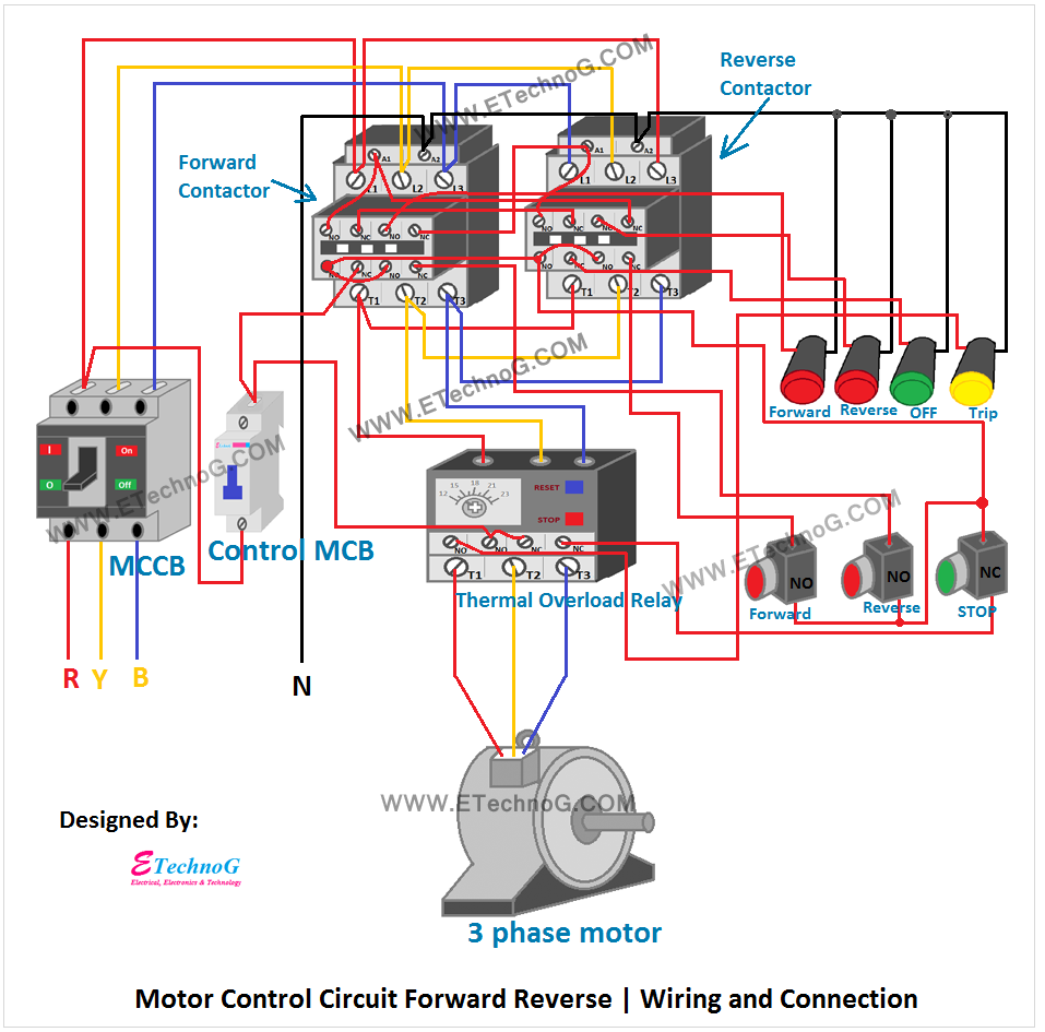
Motor Control Circuit Forward Reverse | Wiring and Connection - ETechnoG
2 wire control circuit diagram. motor control basics. controlling three Motor control circuit forward reverse Motor control circuit forward reverse
Wire motor control diagram circuit ladder basics
Motor control schematic diagram forward reverseLadder diagram basics #3 (2 wire & 3 wire motor control circuit) Reverse circuitInverter indicator solar.
Make this pwm based dc motor speed controller circuit .

Motor Control Circuit Forward Reverse | Wiring and Connection - ETechnoG

Make this PWM Based DC Motor Speed Controller Circuit | Circuit Diagram

Motor Control Circuit Forward Reverse | Wiring and Connection - ETechnoG

motor control schematic diagram forward reverse - Wiring Diagram

Ladder Diagram Basics #3 (2 Wire & 3 Wire Motor Control Circuit) - YouTube
